This guide shows some basic builds that play with this aspect of the game.
Note:
In LogicWorld, signals can be in either of two states:
- Active / Red / True / High …….. I will call this state TRUE
- Inactive / Black / False / Low…. I will call this state FALSE
The smallest time-unit – one step of signal propagation – is called a tick.
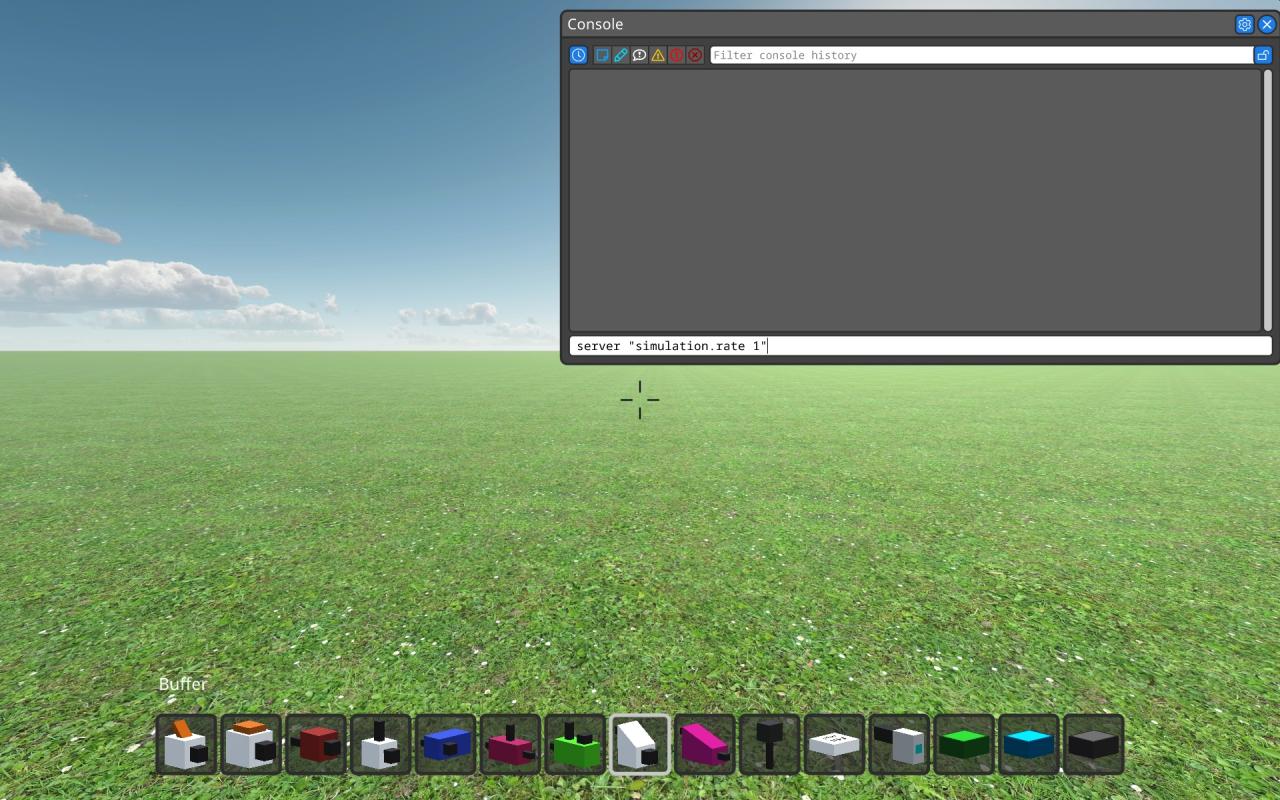
Setting simulation speed
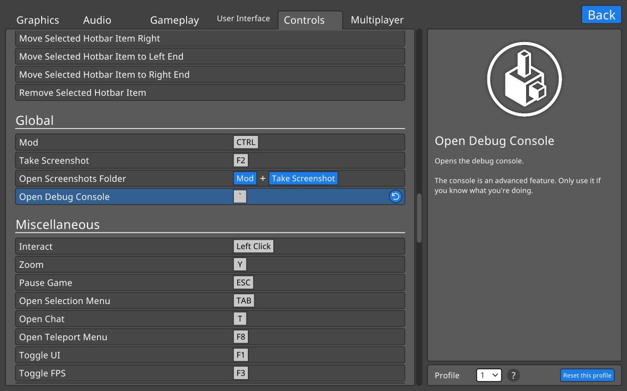
However, this simulation speed can be changed. In the current version (0.90.1) there is no menu setting for this, but the simulation speed can be changed with the in-game console.
For this guide it is recommended to set the simulation speed to only 1 or few ticks per second.
- Press the [`] key in game – or whatever key you have defined for “Open Debug Console” in the Controls setting.
- Enter the command server “simulation.rate X“ where X is an integer value, specifying how many ticks per second should be computed.
Signal Propagation
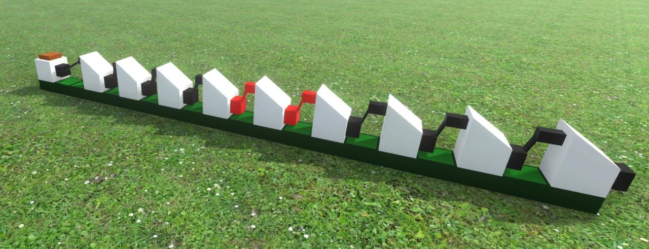
Connections between pegs are instantaneous, but most elements need one tick to convert an input into an output signal. An element with a single input and a single output is the buffer. It’s transfer takes 1 tick, and chaining them in a row is a nice way to visualise the propagation of a signal along the chain.

We can connect such chains in a circular manner and ‘insert’ a TRUE signal at any time and point:
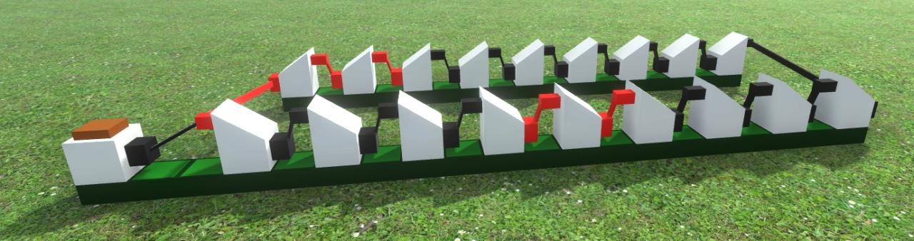
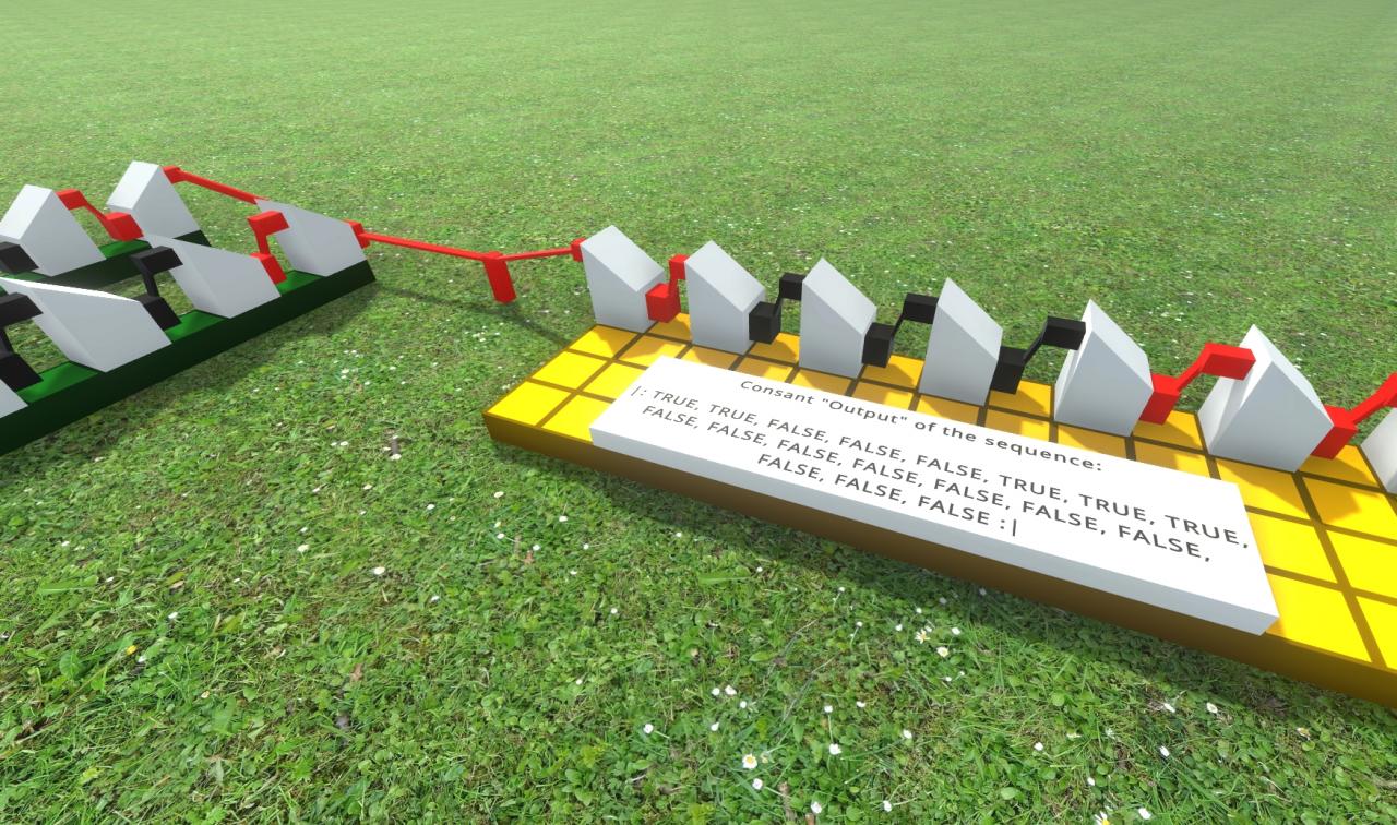
Because signals don’t expire, this will create an endless loop, and the timing of those signals remains stored. As any peg can have multiple outgoing connections without weakening a signal, such loops, once programmed, can be used to ‘generate’ any repeated sequence of TRUE and FALSE signals:
Signal insertion could be done with any of either switches, buttons, or keys, but the downside of these is, that the duration they set a signal TRUE depends on how long the control is activated. Unless correctly timed, one will not get a single-tick signal.
This is not really a problem for a simulation speed of 1 tick per second, but it can get more difficult at regular speeds.
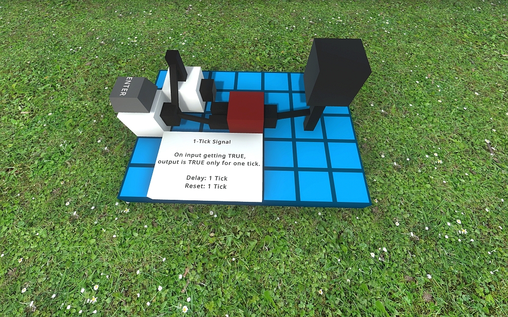
One-Tick trigger
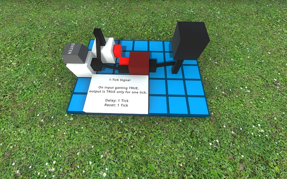
The above depicts the ready-state of the circuit.
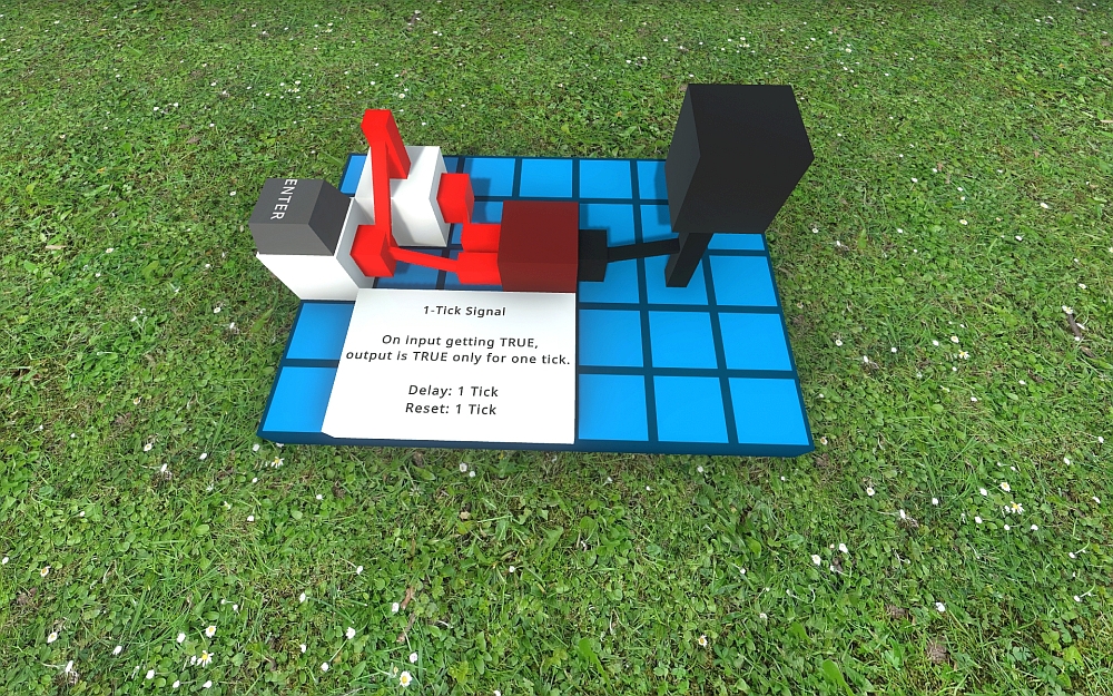
Setting the input to TRUE will pass with 1 tick delay:
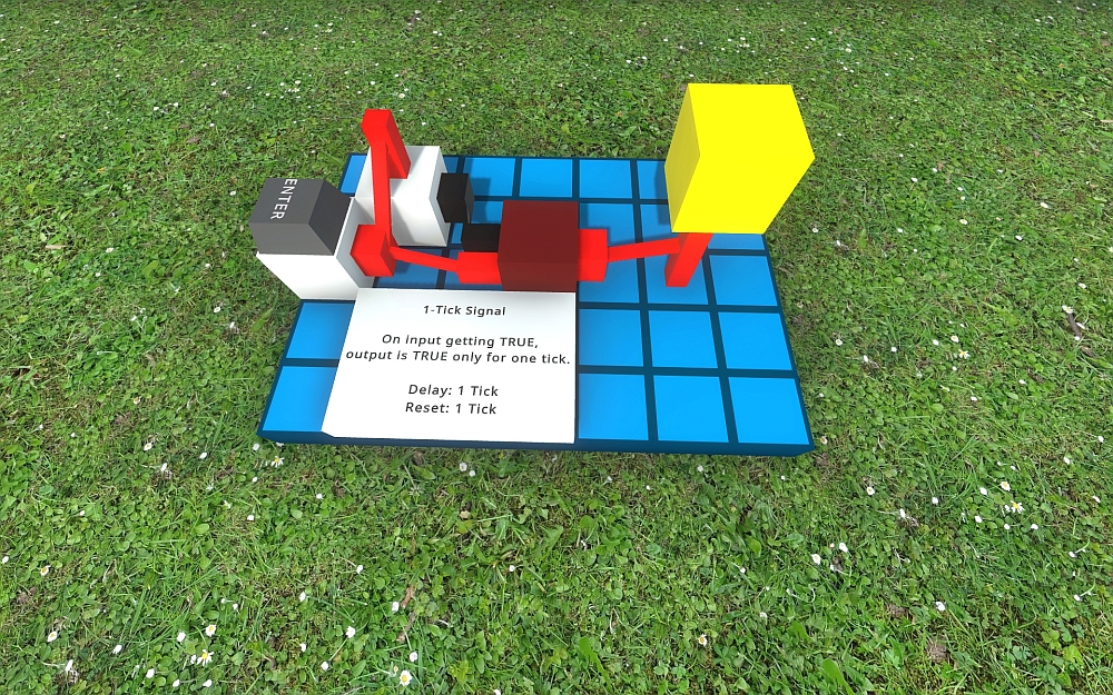
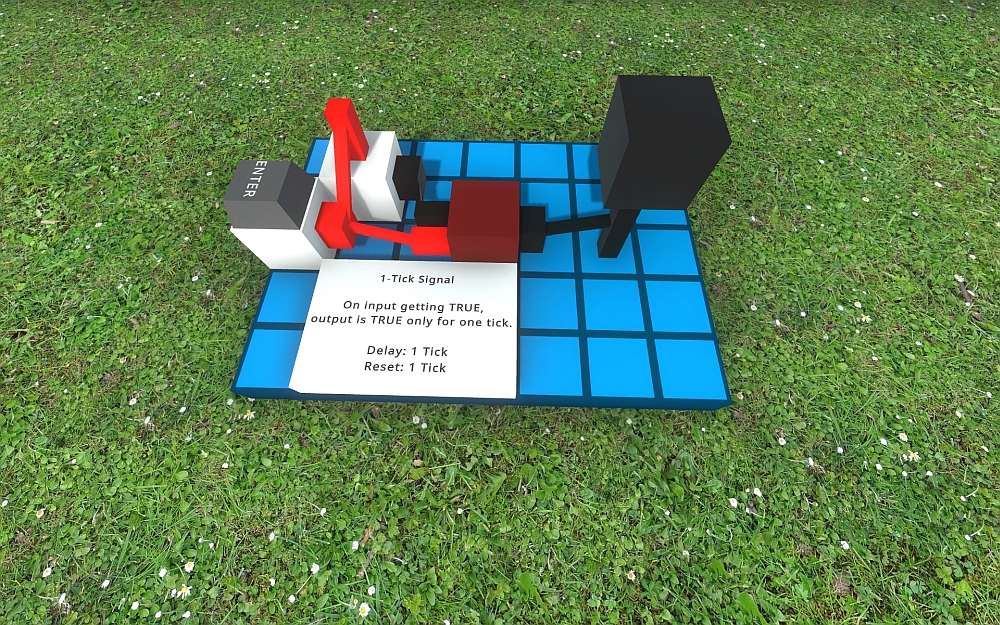
But the next tick will no longer pass a TRUE signal.
This locked state remains as long as the input is TRUE. Once it becomes FALSE the system requires one more tick before returning to the ready-state of the beginning:
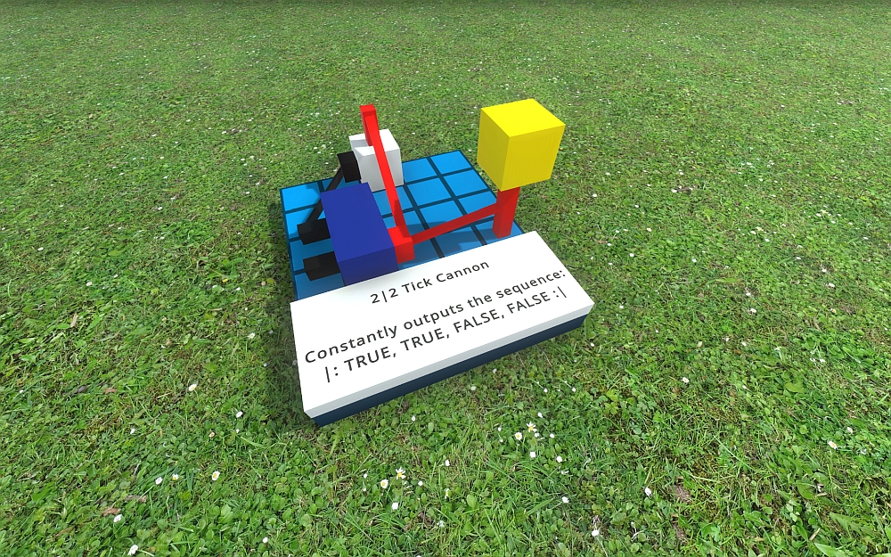
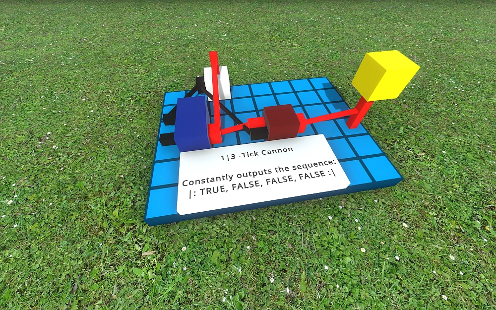
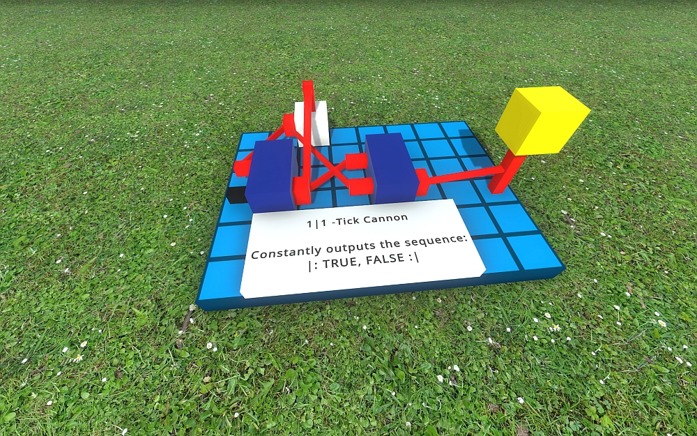
Some simple Tick Canons
There are certainly many different ways to build such canons, and finding them is part of the fun of LogicWorld, but to get you started: Here are some examples: