A guide for showing how to use Retro Gadgets’ various input components and code them to do basic things.
Introduction
This guide is aimed at those who have little to no programming experience and will also serve as a quick crash course on the basics of programming and Lua. I will try to keep this guide as quick and concise as I can.
Assembling the Gadget
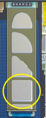
Pull out a second one and connect it to the other one, then use the soldering iron to “fuse” them together.
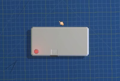
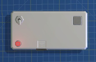
Now, we will start with a simple on/off switch. Go to the inputs drawer, find the switches and place one of your choosing onto your gadget (FYI you can rotate it using a RMB click). I put mine in the left corner to make room for other stuff later. Next, we need an output component of some kind. Head to the output drawer, go to the LEDs and grab a single LED (not a multi-LED) and place it on the right side of your gadget. I chose the square-shaped LED.
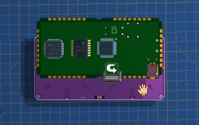
Let’s save some time later and go ahead adding the rest of the parts we’re going to be using in this guide. Place a button, knob, and slider of your choosing (small ones though) onto the left side and then place a small display onto the right side of your gadget, under the LED. I’ve also gone ahead and painted it for visualization purposes, but you don’t have to do that. Here is my setup at this point:
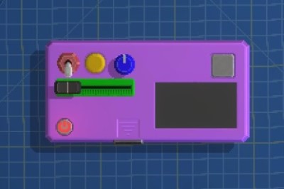
Red: On/off switch
Yellow: Button
Blue: Knob
Green: Slider
We also need a CPU, ROM, and Video Chip from the Misc drawer. Don’t worry, I will explain it all later, but for now just get the smallest of each and place them on your gadget. There won’t be any room on the front of the board so pop the cover off and flip the board over and put them on the back.
Programming for the First Time
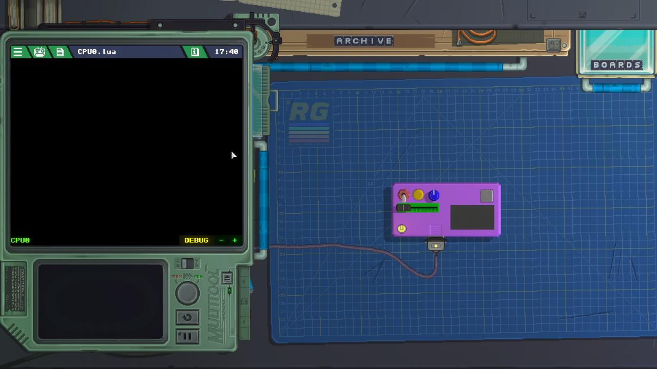
Lua is a very simple, beginner friendly language. If you have never coded before, don’t worry, this guide is aimed for you and I will explain what everything means and how it works. The very first thing we want to do is to turn on the LED. Add the following line of code to your program, keeping in mind that it is case sensitive:
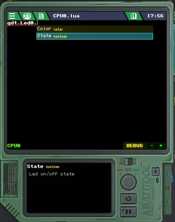
You’ll notice as you typed that a pop up appeared, giving you autofill suggestions. This is a very valuable tool for a new programmer, don’t overlook it. It provides a list of available ways to complete the code, and provides a simple description of what each item means. You can use the up and down arrows to highlight different things and view their descriptions.
Now, let’s examine that line of code we just added:
There are different parts to that code, separated by periods and an equals sign. The first part “gdt” is called a basic space. It is a piece of code that allows you to access the components on the gadget (the switch, buttons, LED, etc) and use it in the current line of code. Think of it like opening a folder on your computer. In order to access the files inside the folder, you have to open the folder first. It works the same way in coding, our components are “files” inside a “folder” that is the gadget itself, and in order to access the components of the gadget we have to “open the folder” by calling the “gdt” basic space. After typing “gdt.” with a period, you’ll see a list of all the components on the gadget.
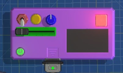
The next part, “Led0” is the name of our LED. You can see the name of any component by clicking on it while the device is off. After adding a period to the end of that, we will be shown two other possible commands: Color, and State. State is a boolean meaning it is either on or off, signified with “true” or “false”. By adding “true” we have enabled our LED to be on whenever the device has power. So, go ahead and hit the power button and see the LED light up.
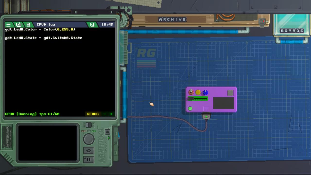
We can change the color too. Enter this code:
There are multiple color options, as you may have seen. We have the option to select a pre-defined color like we just did using the above code (and are given a list of available colors in the autofill popup) or we can make our own color by specifying the RGB values ourselves which we could do like this:
This will also make the LED green. Note that “Color” is capitalized in this one, to differentiate it from the pre-defined color we used before. Lua is case sensitive, always remember that. The three numbers in parentheses are the values of the red, green, and blue respectively, on a scale of 0 to 255. Play around with those numbers and see what kind of colors you get, just remember to separate them with a comma.
Make the LED whatever color you want using whichever method you want, then let’s continue.
Switches
A switch is either on or off. I know, Captain Obvious. I say that because it is a visualization of boolean values. A switch is either on or off, and puts out a boolean “true” or “false” depending on which state it is in.
Delete the Led State code we added before:
You can leave your color code in place if you wish. This code makes it so the LED is on any time the device is powered on. We want it to only come on when the switch is on. This is very easy to do, just use the following line of code:
We are literally saying to the computer “the state of the LED is the same as the state of the switch”. So if the switch’s state is on or “true”, it will make the LED’s state true as well. Let’s hit the power button and see our glorious LED shine with brightness!
.. Uh oh, something is wrong. The LED is not on even after I flipped the switch on. This guide sucks! But wait a second, if I leave the switch on, then turn the power button off and back on again, the LED lights up. Surprise, I just demonstrated the job of the update() function, which is the code that was in our program by default when we created our new gadget and opened the CPU coding screen for the first time. You see, without the update function, the code we enter is only executed once, starting with when we power the gadget on. It will not execute the code again until the next time it is powered on. So, when we power it on, it looks at the state of the switch, sees that the switch is off, and therefore does not turn the LED on. Then when we flip the switch on, nothing happens because the code has already executed, and it is no longer looking for a change in the switch’s state. Likewise, if we leave the switch on, and then power the gadget off and back on again, it executes the code again and sees that the switch is on, and sets the LED to be on as well.
Anyways, in order to use the update() function, simply add this to the very top of your code:
All functions need to have an end, so at the very bottom of your code, simply add a line that just says “end”.
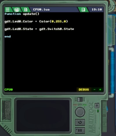
Now power on your gadget and flip the switch a bunch, and you’ll see our LED turns on and off with the switch as we wanted. Congrats!
So, to summarize, anything that has to change live should be placed within an update() function. Such as pushing a button, flipping a switch, moving a slider or knob. Code within the update() function will be executed at every tick. Code outside of it will only execute once.
Buttons, and if/then statements
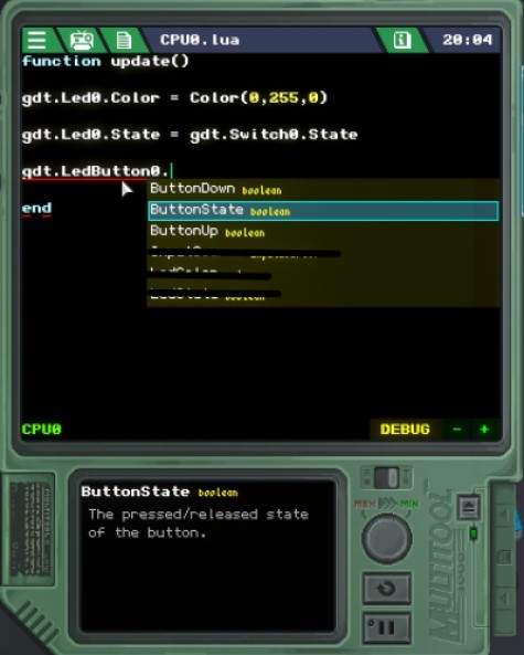
The “ButtonState” command will be the ideal one here, as it will output a value of “true” as long as the button is pressed. The other two will only output for a single tick. That’s not what I want, I want the button to function as long as I am pressing it, so I will use ButtonState in this next task.
We have a switch to turn the LED on and off. We could use the button to do the same thing by replacing the switch code with this:
But I want to use the button to do something else instead, rather than have 2 inputs do the same thing. I want to make the LED change to a different color while I hold the button, and change back when I let go. So, I’ve left the code in place that uses the switch to turn the LED on and off.
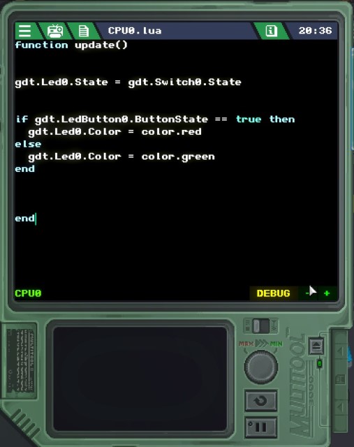
As you can see in the image above, I have changed the color of my LED to green. What if I want the LED to be red when I press and hold the button? We can do that using an if/then statement.
Add the following code to the bottom of the program (but before the “end” of the update function):
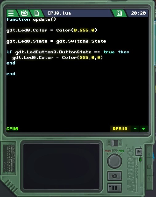
Indenting the second line with a TAB key is good practice for keeping your code organized and readable, but not required.
What this code does is tell the computer “If the button is pushed, then make the LED color red”. When using an if/then statement, you specify a condition – that the button state is “true” or that it is being pressed. When the condition is met, such as when the button is pressed, it will execute the code inside the statement which is to set the LED color to red. Also, notice the double equals signs in the condition line. This is how conditions must be written.
Now when I power my device on and flip the switch, my LED lights up green. When I push the button, it turns red, and goes back to green when I release the button. Hooray! Now, if I didn’t have that “gdt.Led0.Color = Color(0, 255, 0) at the top, the color would not go back to green. It would stay red because there is no code specifying what color it should be if the button is NOT pressed. You could leave it the way I had it, but another way of handling that task would be to add an else after the if/then statement.
It is pretty self explanatory. It says to the computer “if the button state is true, set the LED color to red. Otherwise, set the LED color to green”.
Now, just like before we can flip our light on and toggle the button back and forth to make the LED change colors, and our code looks a little cleaner than before thanks to the if/then statement.
Sliders, Knobs, and variables
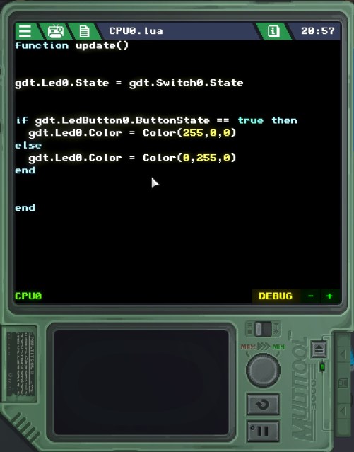
Let’s do something different using the slider. We’ll use it to control the blue level in the LED. In order to do that, let’s change the two “color” functions within the if/then statement from pre-defined colors to RGB instead, like this.
Now, up until this point whenever I’m using the RGB color function, as shown above, I specify the RGB values myself using a hard number. 255 red, 0 green, 0 blue, or 0 red, 255 green, 0 blue. You don’t have to set it by hard-coding it, you can set it using anything that outputs a number. Watch this!
This line of code tells the computer that the red and green values are 0, and that the blue value is whatever the Slider’s value is. But wait, the slider only goes from 0-100 and the RGB range is 0-255! So we have to multiply that slider’s value by 2.55 at the same time!
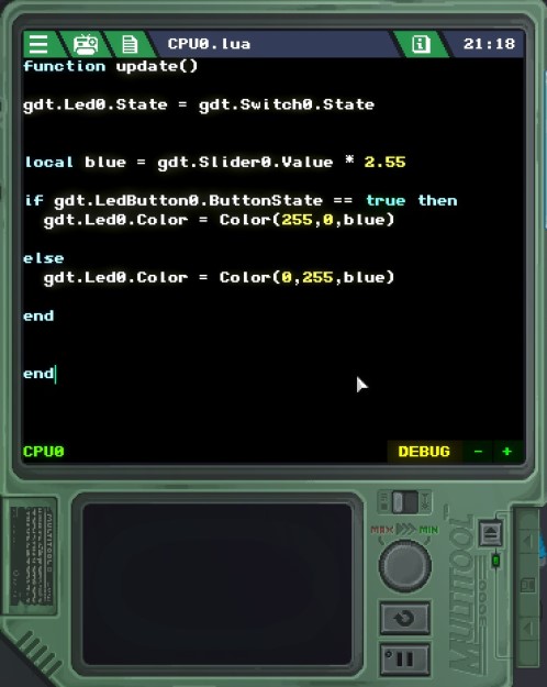
Ok, this is starting to look a little messy. This is where variables come in handy. A variable stores information under a name that you specify. Let’s put all of this blue mumbo jumbo into a variable so that we don’t have to type this whole equation out multiple times. At the top of the program (but within the update function) add:
The word “local” creates a variable, and after that is what you want to call the variable. I have called the variable “blue” because the purpose of the variable is to store the value of the color blue. You can call it whatever you want, though.
Now, instead of typing “gdt.Slider0.Value * 2.55” in place of the blue value in the RGB function, we can just use the name of the variable, which is “blue”:
Now, we can power on our gadget and use the slider to set the blue level of our LED. Pretty cool, huh?
We could use the knob to do the same thing as well, but a knob goes from -100 to 100, so half of it’s range would do nothing because you can’t have a negative RGB value. So instead I’d like to do something else, with it, I want to print the value of the knob onto the screen that we placed all that time ago below the LED.
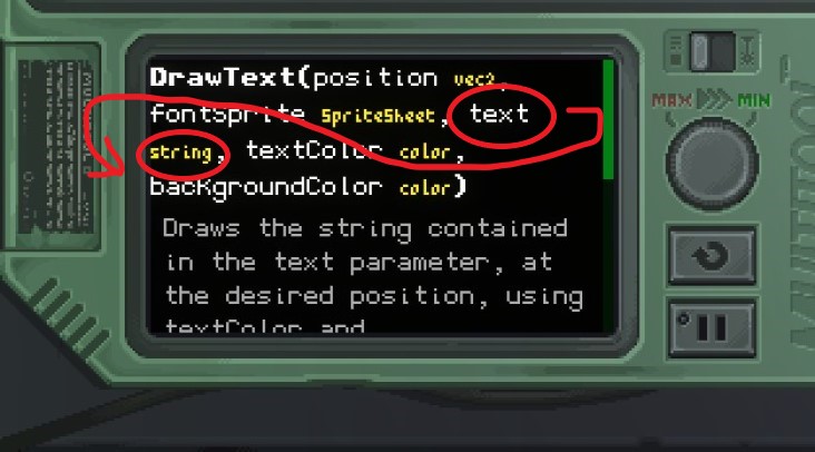
There is already a good guide on how to render text to a screen. Read it here before you continue.
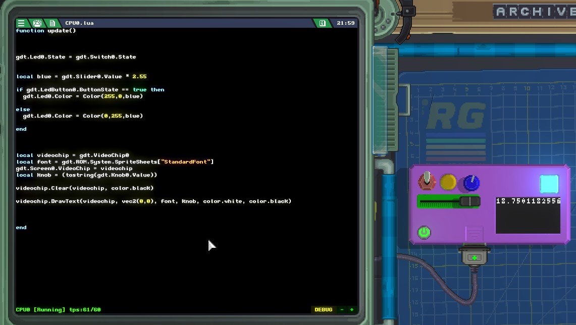
Once you know how to display text to the screen, lets use our screen to display the value of our knob. Add this code to the bottom, separate it from the rest of our code by using a bunch of Return keys. But keep it within the update function!
To clarify what we are doing here step by step, we set the gadget’s Video Chip to a variable called videochip, we set the built-in font to a variable called font, we paired the screen to the videochip, and then created a variable for our knob value. Then we start every tick by clearing the screen and then drawing the text contained in the knob variable to the screen. Hit the power button and let’s see the magic happen!
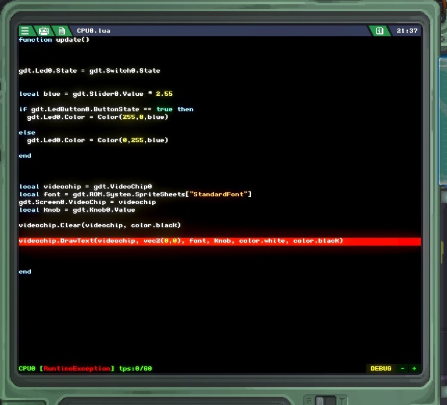
Uh oh, my guide sucks again! Just kidding. We are getting an error because the DrawText command requires the text to be a string, not a number (called an integer in programming). A string is a series of characters that are interpreted literally, in other words displayed exactly as entered.
So in order to display the value of our knob to the screen, we have to convert it’s value to a string. Luckily that is so easy, we only have to modify one single line of code – the line where we create the knob variable. Instead of:
We will modify it like this:
This will convert the value of the knob into a string. Now, we can power on our gadget, and voila!
This is our fully finished product! The switch turns our LED on and off, the button changes it between green and red, the slider controls the blue level, and the screen displays the value of the knob. We are finished!